


OFF
GO LOCAL
| Company | Stock | Price |
|---|---|---|


MIKROE-4580
23 g
Status:
Analog MUX 3 Click is a compact add-on board that switches one of the eight inputs to one output. This board features the ADG738, a CMOS analog matrix switch with a serially-controlled SPI interface from Analog Devices. In an active state, the ADG738 conducts equally well in both directions, making it suitable for multiplexing and demultiplexing applications. It can also be configured as a type of switch array where any, all, or none of eight switches may be closed any time. All channels exhibit ‘break-before-make switching action, preventing momentary shorting when switching channels. This Click board™ is suitable for a wide range of applications, from industrial and instrumentation to medical, consumer, communications, and automotive systems.
Analog MUX 3 Click is supported by a mikroSDK compliant library, which includes functions that simplify software development. This Click board™ comes as a fully tested product, ready to be used on a system equipped with the mikroBUS™ socket.
This product is no longer in stock
Availability date:
OFF
| Company | Stock | Price |
|---|---|---|
Analog MUX 3 Click uses the ADG738, a CMOS 8-channel analog matrix switch with a serially-controlled SPI interface from Analog Devices. The ADG738 can operate equally well as either multiplexer, demultiplexer, or switch array, providing more flexibility. It also features a low on-resistance closely matched between switches and very flat over the entire signal range. During the Power-Up of the ADG738, all switching channels will be in the OFF condition, and the internal shift register will contain all zeros and remains so until a valid write takes place. All channels exhibit ‘break-before-make switching action preventing momentary shorting when switching channels.
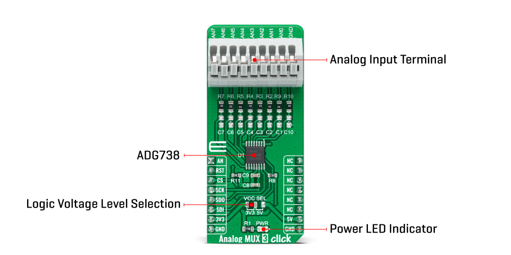
Each bit of the 8-bit serial word corresponds to one switch of the device. Internal switching channels are independently controlled by an individual bit, providing an option of having any, all, or none of the switches activated. All of the input channels of the multiplexer can be easily connected to a nine pole spring action block terminal, without having to use any additional tools, such as screwdrivers, while the output pin from the multiplexer is routed to the AN pin on the mikroBUS™ socket.
When changing the switch conditions, a new 8-bit word is written to the input shift register. Some of the bits may be the same as the previous write cycle, as the user may not wish to change the state of some switches. To minimize glitches on these switches' output, the ADG738 cleverly compares the state of switches from the previous write cycle. If the switch is already in the ON state and needs to stay in that condition, there will be minimal glitches on the switch's output.
Analog MUX 3 Click communicates with MCU using the SPI serial interface compatible with standard SPI, QSPI™, MICROWIRE™, DSP interface standards, and operates at clock rates up to 30MHz. Also, this Click board™ has a Reset pin routed to the RST pin on the mikroBUS™ socket, which clears the input register and turns all switches to the OFF condition.
This Click board™ can operate with both 3.3V and 5V logic voltage levels selected via the VCC SEL jumper. This way, it is allowed for both 3.3V and 5V capable MCUs to properly use the SPI communication lines. However, the Click board™ comes equipped with a library containing easy-to-use functions and an example code that can be used, as a reference, for further development.
Type
Measurements,Multiplexer
Applications
Can be used for a wide range of applications, from industrial and instrumentation to medical, consumer, communications, and automotive systems.
On-board modules
ADG738 - CMOS 8-channel analog matrix switch with a serially-controlled 3-wire SPI interface from Analog Devices
Key Features
8-to-1 matrix switch, low on-resistance, ‘Break-Before-Make’ switching action, serially controlled, and more.
Interface
Analog,SPI
Feature
No ClickID
Compatibility
mikroBUS™
Click board size
L (57.15 x 25.4 mm)
Input Voltage
3.3V or 5V
This table shows how the pinout on Analog MUX 3 Click corresponds to the pinout on the mikroBUS™ socket (the latter shown in the two middle columns).
| Notes | Pin | Pin | Notes | ||||
|---|---|---|---|---|---|---|---|
| Analog Signal | AN | 1 | AN | PWM | 16 | NC | |
| Reset | RST | 2 | RST | INT | 15 | NC | |
| SPI Chip Select | CS | 3 | CS | RX | 14 | NC | |
| SPI Clock | SCK | 4 | SCK | TX | 13 | NC | |
| SPI Data OUT | SDO | 5 | MISO | SCL | 12 | NC | |
| SPI Data IN | SDI | 6 | MOSI | SDA | 11 | NC | |
| Power Supply | 3.3V | 7 | 3.3V | 5V | 10 | 5V | Power Supply |
| Ground | GND | 8 | GND | GND | 9 | GND | Ground |
| Label | Name | Default | Description |
|---|---|---|---|
| LD1 | PWR | - | Power LED Indicator |
| JP1 | VCC SEL | Left | Logic Level Voltage Selection 3V3/5V: Left position 3V3, Right position 5V |
| Description | Min | Typ | Max | Unit |
|---|---|---|---|---|
| Supply Voltage | 3.3 | - | 5 | V |
| Analog Input Signal Range | 0 | - | 5 | V |
| On Resistance | - | - | 4.5 | Ω |
| Operating Temperature Range | -40 | +25 | +105 | °C |
We provide a library for the Analog MUX 3 Click as well as a demo application (example), developed using MIKROE compilers. The demo can run on all the main MIKROE development boards.
Package can be downloaded/installed directly from NECTO Studio Package Manager (recommended), downloaded from our LibStock™ or found on MIKROE github account.
Library Description
This library contains API for Analog MUX 3 Click driver.
Key functions
analogmux3_generic_write Analog MUX 3 data writing function.
analogmux3_set_channel Analog MUX 3 set channel function.
analogmux3_read_an_pin_voltage Analog MUX 3 read AN pin voltage level function.
Example Description
This is an example that demonstrates the use of the Analog MUX 3 Click. This application controls the multiplexing of a single input channel with an eight-channel matrix switch.
 void application_task ( void ) {
     for ( uint8_t ch_pos = ANALOGMUX3_SET_CHANNEL_0; ch_pos <= ANALOGMUX3_SET_CHANNEL_7; ch_pos++ ) {
         analogmux3_set_channel( &analogmux3, ch_pos );
         Delay_ms ( 1000 );

         uint16_t analogmux3_an_value = 0;

         log_printf( &logger, "   CHANNEL    : AN%u     rn", ch_pos );
         log_printf( &logger, "- - - - - - - - - - - - - rn" );

         if ( analogmux3_read_an_pin_value ( &analogmux3, &analogmux3_an_value ) != ADC_ERROR ) {
             log_printf( &logger, "   ADC Value  : %urn", analogmux3_an_value );
         }

         float analogmux3_an_voltage = 0;

         if ( analogmux3_read_an_pin_voltage ( &analogmux3, &analogmux3_an_voltage ) != ADC_ERROR ) {
             log_printf( &logger, "   AN Voltage : %.3f V rn", analogmux3_an_voltage );
         }

         log_printf( &logger, "-------------------------rn" );
     }
 }
The full application code, and ready to use projects can be installed directly from NECTO Studio Package Manager (recommended), downloaded from our LibStock™ or found on MIKROE github account.
Other MIKROE Libraries used in the example:
Additional notes and informations
Depending on the development board you are using, you may need USB UART click, USB UART 2 Click or RS232 Click to connect to your PC, for development systems with no UART to USB interface available on the board. UART terminal is available in all MIKROE compilers.
This Click board™ is supported with mikroSDK - MIKROE Software Development Kit. To ensure proper operation of mikroSDK compliant Click board™ demo applications, mikroSDK should be downloaded from the LibStock and installed for the compiler you are using.
For more information about mikroSDK, visit the official page.
NOTE: Please be advised that any peripheral devices or accessories shown connected to the Click board™ are not included in the package. Check their availability in our shop or in the YMAN section below.

$889.00

$95.00

$549.00

$299.00

$29.00

$29.00

$6.59

$3.60

$119.00

$449.00

$349.00

$349.00

$349.00

$299.00

$269.00

$249.00

$209.00
