


OFF
GO LOCAL
| Company | Stock | Price |
|---|---|---|


MIKROE-1582
35 g
Status:
RS232 Click is a compact add-on board representing a universal usable RS232 transceiver. This board features the MAX3232IDRG4, a low-power, true RS-232 transceiver from Texas Instruments. It provides an interface between the TTL/CMOS logic levels commonly used on microcontrollers and the RS-232 bus. RS-232 is a rather old communication protocol that has survived thanks to its robustness and implementation on many computer motherboards. It can still be found on various pieces of DTE and DCE equipment. This device can achieve speeds up to 232 kbps (EIA/TIA-232). This Click board™ makes the perfect solution for developing notebooks, high-speed modems, battery-powered equipment, hand-held equipment, peripherals, printers, and more.
RS232 Click is supported by a mikroSDK compliant library, which includes functions that simplify software development. This Click board™ comes as a fully tested product, ready to be used on a system equipped with the mikroBUS™ socket.
This product is no longer in stock
Availability date:
OFF
| Company | Stock | Price |
|---|---|---|
RS232 Click is based on the MAX3232IDRG4, a low-power RS-232 transceiver from Texas Instruments. Several protection features improve the reliability of this device. It has up to ±15kV ESD protection, ensuring no electrical discharge damages the circuit on the input side. The MAX3232 has two receivers and two transmitter channels, and it is used to bridge the physical differences between the CMOS/TTL signal levels and RS-232 bus levels. While CMOS/TTL signal levels vary from 0V to 5V typically, RS-232 uses signal levels that range from ±5V up to ±15 V. Furthermore, the RS-232 equipment is required to withstand short circuits for any voltage, up to ±25V, during an indefinite time interval. MAX3232 IC uses two internal charge pumps to obtain required driving levels of ±5V on its transceiver sections.
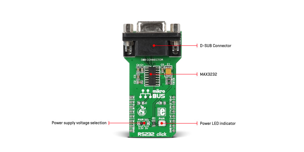
This Click board™ offers two inputs and two outputs, which feature the CMOS/TTL logic levels. These lines can be used to either drive the RS-232 bus or receive the incoming data from the bus. Receivers convert the RS-232 signals to MCU-acceptable UART-type signals, while transmitters convert the MCU UART signal to RS-232 levels. Therefore, one input/output pair is routed to the UART pins of the mikroBUS™, allowing simplified operation by the host MCU, while another pair of input/output signals is routed via the J2 and J3 SMD jumpers and is used as the UART RTS and CTS. These pins are typically used for the UART communication with the hardware flow control. The jumpers are unpopulated by default.
The MAX3232 device can maintain a 120kbps data rate with the worst-case scenario - load of 3kΩ in parallel with 1000pF, while the typical communication speed goes up to 232 kbps. The RS232 Click comes equipped with the SUB D connector, typically found on many devices that use the RS-232 interface, and can be used for connection directly to the RS-232 bus.
RS232 uses a standard 2-Wire UART interface to communicate with the host MCU. If using it with soldered J2 and J3 jumpers, then you can use the UART RTS and CTS hardware flow control pins.
This Click board™ can operate with either 3.3V or 5V logic voltage levels selected via the PWR SEL jumper. This way, both 3.3V and 5V capable MCUs can use the communication lines properly. Also, this Click board™ comes equipped with a library containing easy-to-use functions and an example code that can be used as a reference for further development.
Type
RS232
Applications
Can be used for developing notebooks, high-speed modems, battery-powered equipment, hand-held equipment, peripherals, printers, and more
On-board modules
MAX3232IDRG4 - low-power, true RS-232 transceiver from Texas Instruments
Key Features
Integrated ESD protection, EIA/TIA-232 standards, regulated charge pump yields stable RS-232 outputs regardless of power supply, minimum 120kbps data rate under load, jumpers for enabling UART RTS and CTS hardware control flow pins, SUB D connector, and more
Interface
GPIO,UART
Feature
No ClickID
Compatibility
mikroBUS™
Click board size
L (57.15 x 25.4 mm)
Input Voltage
3.3V or 5V
This table shows how the pinout on RS232 click corresponds to the pinout on the mikroBUS™ socket (the latter shown in the two middle columns).
| Notes | Pin | Pin | Notes | ||||
|---|---|---|---|---|---|---|---|
| NC | 1 | AN | PWM | 16 | NC | ||
| NC | 2 | RST | INT | 15 | CTS | UART CTS | |
| UART RTS | RTS | 3 | CS | RX | 14 | RX | UART TX |
| NC | 4 | SCK | TX | 13 | TX | UART RX | |
| NC | 5 | MISO | SCL | 12 | NC | ||
| NC | 6 | MOSI | SDA | 11 | NC | ||
| Power Supply | 3V3 | 7 | 3.3V | 5V | 10 | 5V | Power Supply |
| Ground | GND | 8 | GND | GND | 9 | GND | Ground |
| Label | Name | Default | Description |
|---|---|---|---|
| LD1 | PWR | - | Power LED indicator |
| J1 | PWR SEL | Left | Logic Level Voltage Selection 3V3/5V: Left position 3V3, Right position 5V |
| J2 | J2 | Unpopulated | UART RTS Signal Activation Jumper |
| J3 | J3 | Unpopulated | UART CTS Signal Activation Jumper |
We provide a library for the RS232 Click as well as a demo application (example), developed using MIKROE compilers. The demo can run on all the main MIKROE development boards.
Package can be downloaded/installed directly from NECTO Studio Package Manager(recommended), downloaded from our LibStock™ or found on Mikroe github account.
Library Description
This library contains API for RS232 Click driver.
Key functions
Generic write function.
Generic read function.
Example Description
This example reads and processes data from RS232 clicks.
 void application_task ( void )
 {
 #ifdef RS232_RECEIVER
     rsp_size = rs232_generic_read( &rs232, uart_rx_buffer, PROCESS_RX_BUFFER_SIZE );

     if ( rsp_size == strlen( message ) )
     {
         log_printf( &logger, "Message received: %s", uart_rx_buffer );
         log_printf( &logger, "rn-------------------------rn" );
         memset( uart_rx_buffer, 0, rsp_size );
     }
     Delay_ms( 100 );
 #endif

 #ifdef RS232_TRANSMITTER
     rs232_generic_write( &rs232, message, strlen( message ) );
     log_printf( &logger, "Message sent: %s", message );
     log_printf( &logger, "rn-------------------------rn" );
     Delay_ms( 1000 );
 #endif
 }
The full application code, and ready to use projects can be installed directly from NECTO Studio Package Manager(recommended), downloaded from our LibStock™ or found on Mikroe github account.
Other Mikroe Libraries used in the example:
Additional notes and informations
Depending on the development board you are using, you may need USB UART click, USB UART 2 Click or RS232 Click to connect to your PC, for development systems with no UART to USB interface available on the board. UART terminal is available in all MIKROE compilers.
This Click board™ is supported with mikroSDK - MIKROE Software Development Kit. To ensure proper operation of mikroSDK compliant Click board™ demo applications, mikroSDK should be downloaded from the LibStock and installed for the compiler you are using.
For more information about mikroSDK, visit the official page.
NOTE: Please be advised that any peripheral devices or accessories shown connected to the Click board™ are not included in the package. Check their availability in our shop or in the YMAN section below.

$889.00

$95.00

$549.00

$299.00

$29.00

$29.00

$6.59

$3.60

$119.00

$449.00

$349.00

$349.00

$349.00

$299.00

$269.00

$249.00

$209.00
